MIL-O-81151A(OS)
4.4.4.9.2 Connect the oscilloscope (4.4.3.3) to pin 1 of the oscillator
subassembly,
4.4.4.9.3 Observe the waveform on the oscilloscope. The wave shall be
sinusoidal and shall not contain noise or spikes (transients).
4.4.4.9,4 Remove the oscilloscope lead from pin 1 and connect the wave
analyzer (4.4.3.4) to pin 1 of the oscillator subassembly.
4.4.4.9.5 In accordance with the instructions provided with the wave
analyzer, measure and record the amplitude of the fundamental and the
amplitudes of es many harmonics as possible.
4.4.4.9.6 Using the values recorded in 4.4.4.9,5 and the formula given
in 3.4.4 compute the distortion factor "D", The distortion factor "D"
shall not exceed two percent.
4.4.4.9.7 Remove the wave analyzer lead from pin 1 of the oscillator
subassembly.
4.4.4.10 To measure the phase difference as set forth in 3.4.5:
4.4.4.10.1 In accordance with the instructions provided with the
Universal EPUT meter (4.4.3.2), set the meter controls for Time-Interval-
Meter (TIM) Operation.
4.4.4.10.2 Connect pin 1 of the oscillator subassembly to the B input
channel.
4.4,4.10.3 Connect pin 7 of the oscillator subassembly to the A input
channel,
the ATTEN. selector
4.4.4.10.4 With the TIME-SECONDS selector on
on 10 ac, both TRIGGER VOLTAGE controls to their center positions and the
read the count on the EPUT meter,
SLOPE switches on plus
4.4.4.10.5 Set the SLOPE switches to minus (-), and read the count. If
this reading is not the same es 4.4.4.10.4, adjust the TRIGGER VOLTAGE con-
trols until the count is the same for both plus and minus SLOPE switch
settings.
4.4.4.10.6 Record the count.
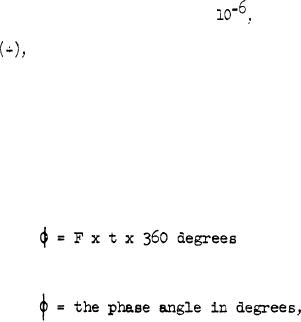
4.4.4.10.7 Compute the phase angle from the following formula:
where,
12
For Parts Inquires call Parts Hangar, Inc (727) 493-0744
© Copyright 2015 Integrated Publishing, Inc.
A Service Disabled Veteran Owned Small Business