MIL-C-82630(OS)
4.5 Test methods
4.5.1 General. The methods employed for testing component materials and cable performance
shall be as specified in MIL-C-19787, except as modified or supplemented herein.
4.5.1.1 Visual and dimensional inspection. The sample length of cable selected under
4.3.2 shall be examined visually and dimensionally for compliance with the requirements of
this specification and other applicable specific ations. In addition, each manufactured
length of cable shall be examined visually for surface flaws such as pin holes and pushbacks
in the sheath and shall be cut at any such defects.
4.5.2 Cable sheath. One sheath specimen shall be taken from each of the cable samples cho-
sen for insulation testing, for physical tests to determine compliance with MIL-R-6855 and
the requirements of 3.3.5.
4.5.3 Dielectric strength. A length of completed cable shall be tested dry, without immer-
sion in water, in accordance with Federal Test Method Standard No. 228 (Method 6111) to de-
termine conformance with 3.4.1.
4.5.4 Insulation resistance. A length of completed cable shall be tested dry, without im-
mersion in water, in accordance with Federal Test Method Standard No. 228 (Method 6031) to
determine conformance with 3.4.2.
4.5.5 Cable lay. The sample chosen for dielectric testing shall be examined to determine
compliance with the requirements of 3.3.4. This examination is to be done after the comple-
tion of the dielectric test.
4.5.6 Capacitance. The samples used shall be prepared in accordance with 4.5.6.1 and shall
be 20 feet (6 metres) in length. The measurement technique employed shall give results that are
reproducible to three significant figures.
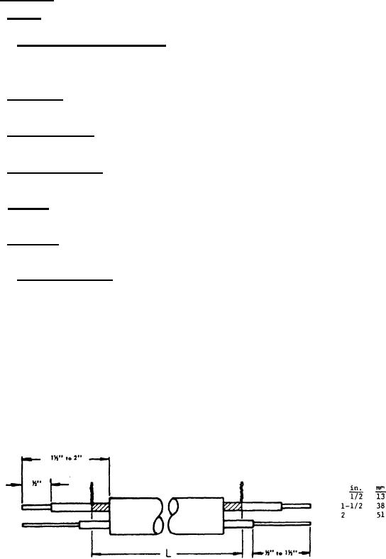
Prepare each 20-foot (6 metre) minimum length of cable as
4.5.6.1 Preparation for tests.
follows (see Figure 3):
(a) Strip back cable sheathing 1 1/2 to 2 inches (40 to 50 mm) on each end of sample for
connections.
(b) Comb out shielding on each of the seven shielded conductors to within approximately
1/2 inch (12 mm) of the sheathing.
(c) Strip approximately 1/2 inch (12 mm) of insulation from each shielded conductor.
NOTE: For computation purposes, the length of the cable shall be considered
as the distance between the undisturbed ends of the shielding.
4.5.6.2 Test the prepared length of cable to determine conformance with 3.4.3.
Preparation of Sample for Capacitance Test.
Figure 3.
8
For Parts Inquires call Parts Hangar, Inc (727) 493-0744
© Copyright 2015 Integrated Publishing, Inc.
A Service Disabled Veteran Owned Small Business